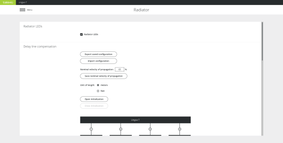
On the transmitter web server you can configure different radiator settings. You can only access and configure the radiator through the transmitter. On the radiator page you can choose to disable the radiator status LEDs. In order not to distract, the status LEDs of the radiators can be switched during a meeting.
Figure 6-1 The Radiator page
You can also select the information the LEDs display. This is convenient when setting up the system. To change the LED indication mode click Open initialization. The following options are available:

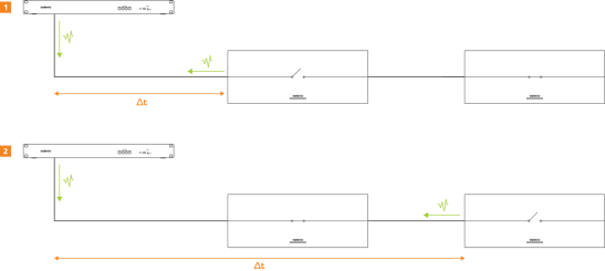
When two or more radiators have overlapping footprints then the signal of these radiators can cancel each other out in the overlapping areas. This is the case when the length of the cable differs between the different radiators, due to the delay of the signal ( ) over the cable. This can lead to black spots, where you are unable to receive the infrared signal of the radiators using the receivers.
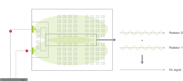
Figure 6-2 The relation between the delay of a signal in the cable and the signal picked up by the receiver. When the infrared signals of the radiators are asynchronous, they cancel each other out. As a result the receiver will have no audio.
To prevent this effect you need to compensate for this delay. This means that the radiators need to send their signal at the same time of that of the slowest radiator, delaying their signal until the slowest radiator receives the data. The slowest radiator is the one which has the longest cable between the transmitter and the radiator.
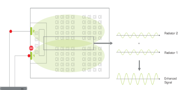
Figure 6-3 After delay line compensation the radiator halts the transmission of its infrared signal until the slowest radiator also receives the signal.
The CoCon system has an automatic delay line compensation mechanism where the software measures the delay based on pulses it sends over the cable. Based on the results it will specify the delay as a multiple of 25 ns (for 71.98.0223) or 12,5 ns (71.98.0220). The web server will also give a visual representation of all radiators and their distance to the transmitter.
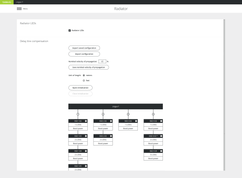
Figure 6-4 Automatic delay line compensation calibration using the CoCon web server
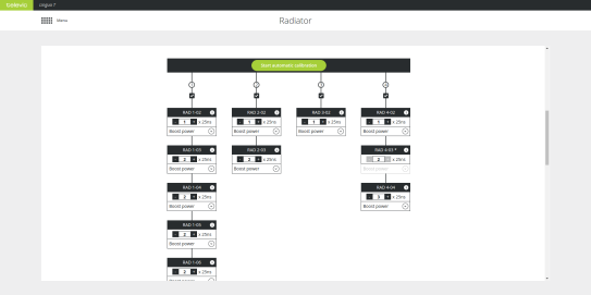
Figure 6-5 How to start automatic delay line compensation calibration using the CoCon web server
To measure the distance between the transmitter and the radiator, the transmitter sends out a pulse to the radiator. The transmitter then measures the time (timeinterval: ∆t) it takes until the pulse is reflected by the radiator. When there are multiple radiators on one port, the switch of the radiators are closed sequentially to measure the distance to the next radiator in line.
When the calibration is ready, you get an overview of all radiators per transmitter port. Per radiator you can adjust the delay line compensation as well as the power level. However, when you have a previous version of the radiator (71.98.0223) it is not possible to change the power level (it is greyed out). These radiators are indicated by an asterisk *.
When you use infrared, sometimes interference from other systems using the same frequency can occur. In these cases you can disable bands.
On the Radiator page of the web server go to Disable occupied infrared bands, where you can disble infrared bands to avoid interference from other systems that use the same infrared band such as IR wireless microphones. Select those bands you want to disable and select Save settings.
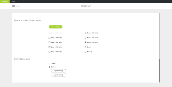
Figure 6-6 Configure infrared bands using the CoCon web server
With this setting you can configure the gain of individual infrared bands (see figure Figure 6-6 ). There are two options available:
When your system contains third-party equipment, or you want to finetune the infrared band gains, you can upload a settings file containing the desired band gain values.